Guide to Setup Arduino in Micromanager
Arduino setup device firmware in Micromanager:
| Summary: | Adapter for the Arduino electronics prototyping platform |
|---|---|
| Author: | Nico Stuurman |
| License: | LGPL |
| Platforms: | Linux, Mac, and Windows |
| Since version: | 1.3.18 |
| Automated Serial Port Setup: | Yes |
| Peripheral device discovery: | No |
| Wiki page: | Nico Stuurman Pariksheet Nanda Roy Wollman |
The Micro-Manager interface to the Arduino consists of an Arduino program (the ‘firmware’) that you need to upload to the Arduino first. The current version of the Micro-Manager has facilities to use the Arduino as a shutter, and as a shutter that only opens when a TTL is set high (for instance, when the camera is exposing). Also, timed sequences of TTL output can be setup.
Firmware
For the Arduino Uno and similar boards, download the firmware source code. Bonno Meddens wrote compatible firmware for the ESP32, ItsyBitsy M4, and Teensy 3.x boards that can be found here. Copy the firmware into a blank Arduino Sketch window. Send to the Arduino, and your Arduino is programmed to work with Micro-Manager.
Hardware Configuration Wizard
Hub
Add the Arduino-Hub. You may want to set the “Verbose” property of the port to 0 to avoid extensive logging of the communcation with the device, especially if you are using the input functionality (which queries the Arduino every second).
| Pre-Initialization Properties | Description |
|---|---|
| Logic | Inverted causes digital inputs and outputs to be considered HIGH when 0 Volts and LOW when +5 Volts. |
| Serial Setting | Value |
|---|---|
| AnswerTimeout | 500 |
| BaudRate | 57600 |
| DelayBetweenCharsMs | 0 |
| Handshaking | Off |
| Parity | None |
| StopBits | 1 |
| Verbose | 0 |
Peripheral Devices Setup
| Name | Description |
|---|---|
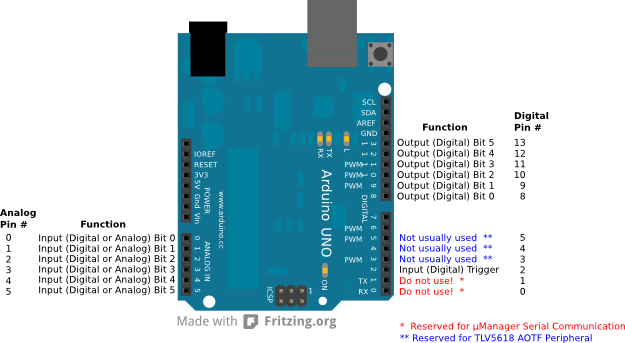
| Arduino-Switch | Digital output pattern set across pins 8 to 13. See usage in Digital IO. |
| Arduino-Shutter | Toggles the digital outputs pattern across pins 8 to 13. Set all pins off when the shutter is closed, and restores the value set in Switch-State when the shutter is opened. |
| Arduino-Input | Reports, both, the digital and analog (0-1023) state of the analog input pins 0 to 5. |
| Arduino-DAC{1,2} | (Not usually used) Reserved for TLV5618 AOTF Peripheral. TLV5618 is a chip acting as a DAC (digital-to-analog converter) that can be added as a shield to the Arduino. This way, the Arduino can be used to control analog devices such as AOTF or stages. See DAC. |
| Initialization Properties | Description |
|---|---|
| Pin | Reads all 6 input pins when set to All, otherwise reads the individual 0-5 Pin number. |
| Pull-Up-Resistor | Choose whether the Arduino should use its internal 20 kOhm internal pull-up resistor. If not sure, choose On. |
Usage Notes
Digital IO
All possible combinations of digital outputs that can be set across pins 8 to 13 can be set by a single number from from 0 to 63, with 0 turning off all pins and 63 turning all pins on.
To choose the set of pins to be on for your Arduino-Switch-State ==pattern, simply add all the decimal values for the pin from the table below; so for pins 8 and 10 to be on, needs a decimal value of 1 + 4 = 5 to be set in== Arduino-Switch-State.
| Pin | Bit | Decimal Value when On | LED State |
|---|---|---|---|
| 8 | 0 | 1 | strobe |
| 9 | 1 | 2 | violet |
| 10 | 2 | 4 | blue |
| 11 | 3 | 8 | --- |
| 12 | 4 | 16 | --- |
| 13 | 5 | 32 | --- |
The reason one has to do this is MM encodes the pins as bits in binary. Pin 13 corresponds to the most significant bit 5, whose decimal value is 2^5 = 32. Similarly pin 10 will be bit 2 which has a decimal value of 2^2 = 4.
Blanking
The “blanking” feature of the device adapter allows to ensure that the sample is illuminated only when the camera is exposing. By connecting a TTL output of the camera (active when the camera is exposing) to the arduino input and enabling blanking, the digital output of the arduino will be kept at zero as long as the TTL is inactive.
Device Properties
| Properties | Description |
|---|---|
| Switch-Blanking Mode | Allows On or Off: enables “blanking” when the TTL input is inactive. |
| Switch-Blank On | Allows Low or High: defines the active state of the TTL input. |
| Switch-HubID | |
| Switch-Label | Set the digital output pattern across pins 8 to 13. Allows values 0-63. See usage in Digital IO |
| Switch-Sequence | Off operates the Arduino in normal “switching” mode. On enables triggered “sequencing” mode. The digital input signal to pin 2 switches between the uploaded patterns. Typically, one would connect the camera exposure signal to pin 2. |
| Switch-State | Set the digital output pattern across pins 8 to 13. Allows values 0-63. See usage in Digital IO |
| Input-AnalogInput{0:5} | 10-bit value of ADC input. |
| Input-DigitalInput | Value depends on how the Pin initialization property was set. Shows binary state of the input pin, if a single in was selected. Shows the 5-bit value of all input pins if “All” was selected. |
| Input-HubID | |
| DAC{1,2}-HubID | (Not usually used) Reserved for TLV5618 AOTF Peripheral. |
| DAC(1,2}-Volts | (Not usually used) Reserved for TLV5618 AOTF Peripheral. |
Discussion page for Arduino imported from old wiki